20BE125A0ANNANB0
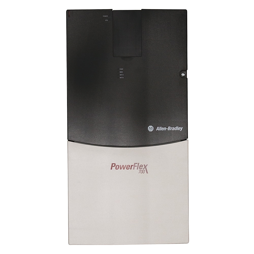
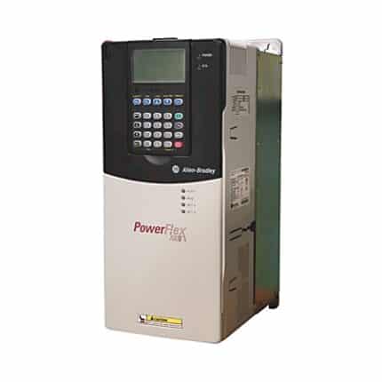
20BE125A0ANNANB0 Allen Bradley PowerFlex 700 AC Drive 20B.
Technical Specifications
Mechanical
| Degree of protection (IP) | IP20
20BE125A0ANNANB0 |
|---|---|
| Shock | 15 G peak for 11 ms duration (±1.0 ms) |
| PWM frequency | 2 kHz @ 600V AC |
| Vibration | 0.152 mm (0.006 inch) displacement, 1 G peak |
Electrical
| Number of analogue outputs | 2 |
|---|---|
| Mains voltage | 600 V |
| Integrated breaking resistance | No |
| Brake IGBT | Without brake IGBT |
| Internal communication module | No communication module |
| Input voltage rating | 600V AC, 3-phase, 60 Hz |
| AC input undervoltage trip | Frames 0…4: 345V AC @ 600V |
| Bus voltage, nom | Frames 0…4: 810V DC @ 600V |
| Bus undervoltage shutoff/fault | Frames 0…4: 381V DC @ 600V |
| Bus overvoltage trip | Frames 0…4: 1013V DC @ 600V |
| Output voltage rating | 0…575V AC @ 600V AC, 1-phase |
| Circuit breaker current rating, max | 375 A @ 600V AC, 3-phase, normal duty |
| Motor circuit protector current rating, max | 250 A @ 600V AC, 3-phase, normal duty |
| Output current rating, continuous | 99 A @ 600V AC, 3-phase, heavy duty |
| Output current rating, 1 min | 149 A @ 600V AC, 3-phase, heavy duty |
| Output current rating, 3 sec | 198 A @ 600V AC, 3-phase, heavy duty |
| Logic control ride-thru | 0.5 seconds minimum, 2 seconds typical |
| Brake resistor | No internal brake resistor |
| Input current rating | 93 A @ 600V AC, 3-phase |
| Documentation | Manual of 20BE125A0ANNANB0 |
| Carrier frequency | 2, 4, 8, and 10 kHz. Drive rating based on 4 kHz |
| Encoder quadrature | 90 degrees, ±27 degrees at 25 °C (77 °F) |
| AC input overvoltage trip | Frames 0…4: 716V AC @ 600V |
| Input power rating | 96.6 kVA @ 600V AC, 3-phase, heavy duty |
| Dual element time delay fuse current rating | 150…250 A @ 600V AC, 3-phase, normal duty |
| Non-time delay fuse current rating | 150…375 A @ 600V AC, 3-phase, normal duty |
| Digital input latency, typical | 9.2 ms @ stop signal for SVC motor control |
| Heat sink thermistor | Monitored by microprocessor overtemp trip |
| Digital input latency | 9.2…16.0 ms @ start signal for SVC motor control |
| Drive to motor power ratio, max | Recommended not greater than 2:1 ratio |
| Stop modes | Multiple programmable stop modes including — Ramp, Coast, DC-brake, Fast brake, Ramp-to-hold and S-curve |
| Frequency accuracy | Digital input: within ±0.01% of set output frequency |
| Acceleration/deceleration | Two independently programmable accel and decel times. Each time can be programmed from 0…3600 seconds in 0.1 second increments |
| Analog input latency, typical | 6.4 ms @ speed signal for SVC motor control |
| Number of digital inputs | 6 |
| Number of digital outputs | 3 |
| Number of analogue inputs | 2 |
| Internal watts loss | 500 W @ 600V, 125 Hp normal duty (IP20, NEMA/UL Type 1) |
| Motor voltage, nom | 690V @ 500…690V drive rating, 690V nominal line voltage |
| Supporting protocol for DeviceNet | Yes |
| Human interface model | No HIM (blank plate inserted) 20BE125A0ANNANB0 |
| Max. output frequency | 400 Hz |
| External watts loss | 1584 W @ 600V, 125 Hp normal duty (IP54, NEMA/UL Type 12) |
| Total watts loss | 1900 W @ 600V, 125 Hp normal duty (IP54, NEMA/UL Type 12) |
| Supporting protocol for EtherNet/IP | Yes |
| Line voltage, nom | 690V @ 500…690V drive rating, 690V nominal motor voltage |
| Mains frequency | 60 Hz |
| Actual short circuit rating | Determined by AIC rating of installed fuse/circuit breaker |
| Internal EMC filtering | With EMC filter with common mode choke |
| Custom drive/firmware | No custom firmware |
| Feedback option | No feedback |
| Analog input latency | 4.8…12.4 ms @ speed signal for SVC motor control |
| Drive full power range | 690…759V @ 500…690V drive rating |
| Drive operating range | 475…759V @ 500…690V drive rating |
| Torque regulation | Without feedback: ±5 %, 600 rad/sec bandwidth |
| Enclosure type | IP20/NEMA/UL Type 1 |
| Output current rating | 62.5 A @ 600V AC, 1-phase |
| Control options | Standard control with 115V AC I/O |
| Drive overcurrent trip | Instantaneous current limit: 220…300% of rated current (dependent on drive rating) |
| Efficiency | 97.5% at rated amps, nominal line volts |
| Encoder supply | 12V, 250 mA. 12V, 10 mA minimum inputs isolated with differential transmitter, 250 kHz maximum |
| Speed control-speed regulation | Without feedback (Vector Control Mode): 0.1 % of base speed across 120:1 speed range, 120:1 operating range, 50 rad/sec bandwidth |
| Current limit capability | Proactive current limit programmable from 20…160% of rated output current, Independently programmable proportional and integral gain |
| Selectable motor control | Sensorless vector with full tuning. Standards V/Hz with full custom capability and vector control |
| Frequency control-speed regulation | With slip compensation (Volts per Hertz mode): 0.5% of base speed across 40:1 speed range, 40:1 operating range, 10 rad/sec bandwidth |
| Input phases | 3-phase input provides full rating for all drives. 1-phase operation possible on certain drives and provides 50 % of rated current. Frames 0…6: drive can be supplied as 6 pulse or 18 pulse in an engineered package. |
| Control method | Sine coded PWM with programmable carrier frequency, ratings apply to all drives, the drive can be supplied as 6 pulse or 18 pulse in an engineered solution |
| Encoder requirements | Encoders must be line driver type, quadrature (dual channel) or pulse (single channel), 8…15V DC output (4…6V DC when jumpers are in 5V position), single-ended or differential and capable of supplying a min. of 10 mA per channel, maximum input frequen |
| Number of phases output | 3 |
| Number of phases input | 3 |
| Relative symmetric net voltage tolerance | 10 % |
| With control element | Yes |
| Supporting protocol for LON | Yes |
| Supporting protocol for TCP/IP | Yes |
| Supporting protocol for PROFIBUS | Yes |
| Supporting protocol for CAN | Yes |
| Supporting protocol for Modbus | Yes |
| Motor overload protection | Frames 0…6 standard control: powerflex 700 drives with standard control, which is identified by an N, A, or B in position 15 of the catalog number, only provide Class 10 motor overload protection according to NEC article 430, they do not provide speed |
| Input frequency tolerance | 47 Hz |
| Encoder duty cycle | 50% ±10% |
| Displacement power factor (all drives) | 0.98 across speed range |
| Short circuit rating, max | 200000 amps symmetrical |
| Output voltage range | 0 to rated motor voltage |
| Encoder type | Incremental, dual channel |
| Power ride-thru | 15 milliseconds at full load |
| Short circuit trip | Phase-to-phase on drive output |
| Ground fault trip | Phase-to-ground on drive output |
| Drive to motor power ratio, min | Recommended not less than 1:2 ratio |
| Control logic noise immunity | Showering arc transients upto 1500V peak |
| Line transients | Up to 6000 volts peak per IEEE C62.41-1991 |
| Intermittent overload | 110% overload capability for up to 1 minute, 150% overload capability for up to 3 seconds |


